Displacement
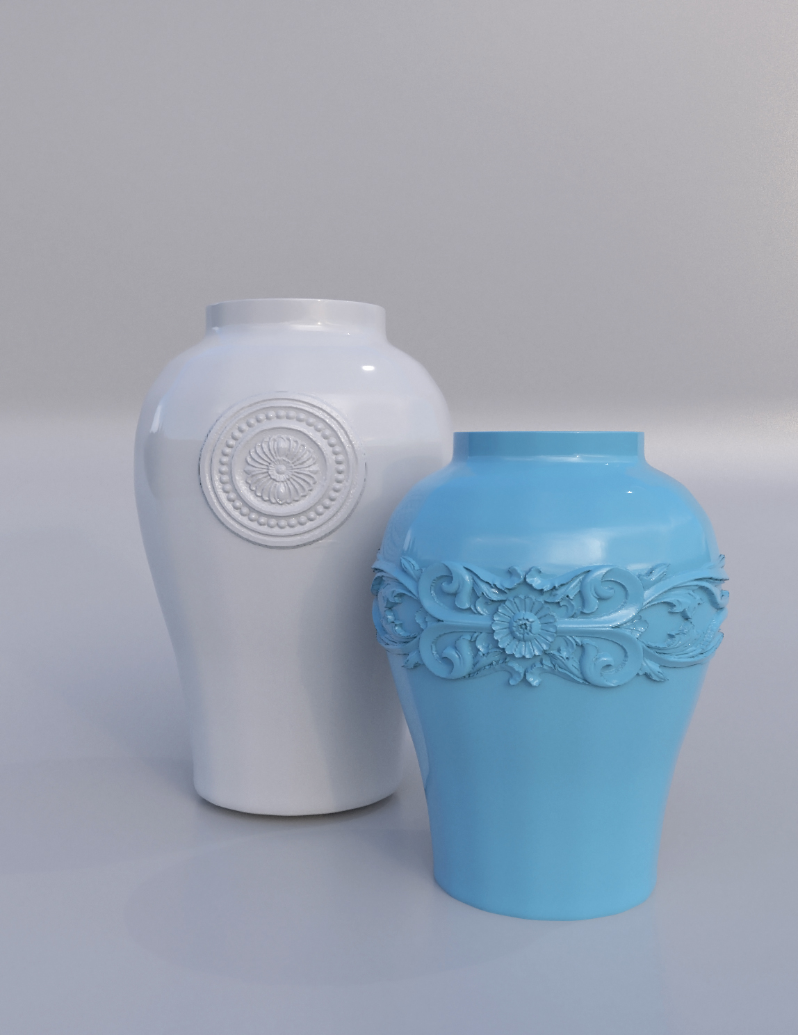
The displacement component is used to displace the surface geometry based on a texture map. Displacement can help to create realistic surface details without the need to spend additional time on modeling. Unlike normal mapping which only simulates surface details, displacement provides for the true surface relief and correct shadowing effects, as it physically changes the positions of vertices, edges and faces of the mesh.
Displacement of the surface geometry should be supported by a sufficient number of polygons so as to give the object a smooth appearance. Additional polygons can be created by using the object’s subdivision properties within the displacement component. Note, however, that subdivision requires extra computational and memory resources and will normally slow down the rendering process.
In AMD Radeon ProRender, the displacement component can be controlled using the following parameters:
Displacement Min/Max
The Displacement Min/Max parameters control the displacement scale, i. e. the distance by which the geometry should be displaced. These minimum and maximum values correspond to the black and white colors of the grayscale displacement map. The minimum value controls the displacement scale for the black color, while the maximum value controls it for the white color.
The displacement distance is automatically adjusted to the scene measurement units. The input type for this parameter is a numeric value equal to or greater than 0. Note that the input cannot be a negative value, that is, displacement is done in the outward direction only (extrusion).
In the example image below, if the displacement Min value is 0 and the Max value is 0.03, the black color will not be displaced, while the white colors will be extruded. If the min and max values are swapped, the black colors will be displaced, while the position for the white color will not be altered.
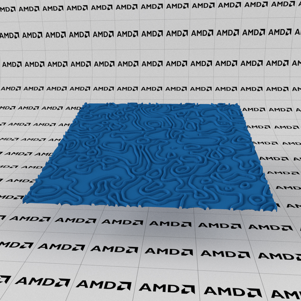
Min: 0, Max: 0.03 |
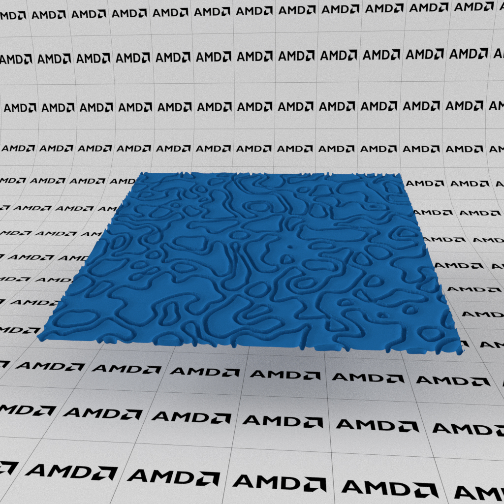
Min: 0.03, Max: 0 |
Subdivision Type
For a convincing displacement effect and smooth appearance, the object’s surface should have a sufficient number of polygons. AMD Radeon ProRender offers the two subdivision methods for smoothing the surface: level subdivision and adaptive subdivision.
AMD Radeon ProRender relies on OpenSubdiv to implement surface subdivision. See OpenSubdiv documentation for details.
Level Subdivision
Using level subdivision, polygons are subdivided uniformly. Each polygon is divided n times, where n is the subdivision factor. Greater subdivision values produce smoother mesh and, therefore, result in a more precise displacement, but require more resources and time to render.
The input type for the level subdivision factor is an integer.
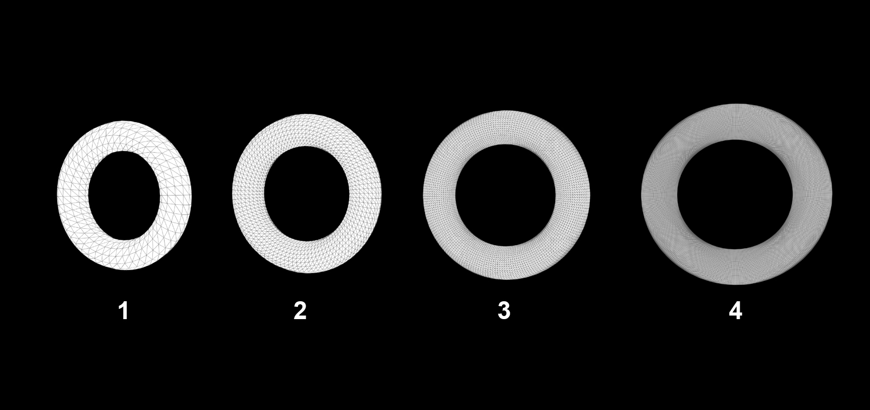
Level subdivision factor: 1, 2, 3, 4 |
Adaptive Subdivision
Using adaptive subdivision, the number of new polygons added depends on the proximity of the object to the camera. The adaptive subdivision factor determines the size of the resulting micro-polygons in pixels.
This method helps to optimize the resource usage, as objects closer to the camera are subdivided into a greater number of polygons, have finer geometry and more precise displacement. In contrast, for objects positioned further from the camera, the number of polygons will be smaller.
The input type for the adaptive subdivision factor is a number equal to or greater than 0.
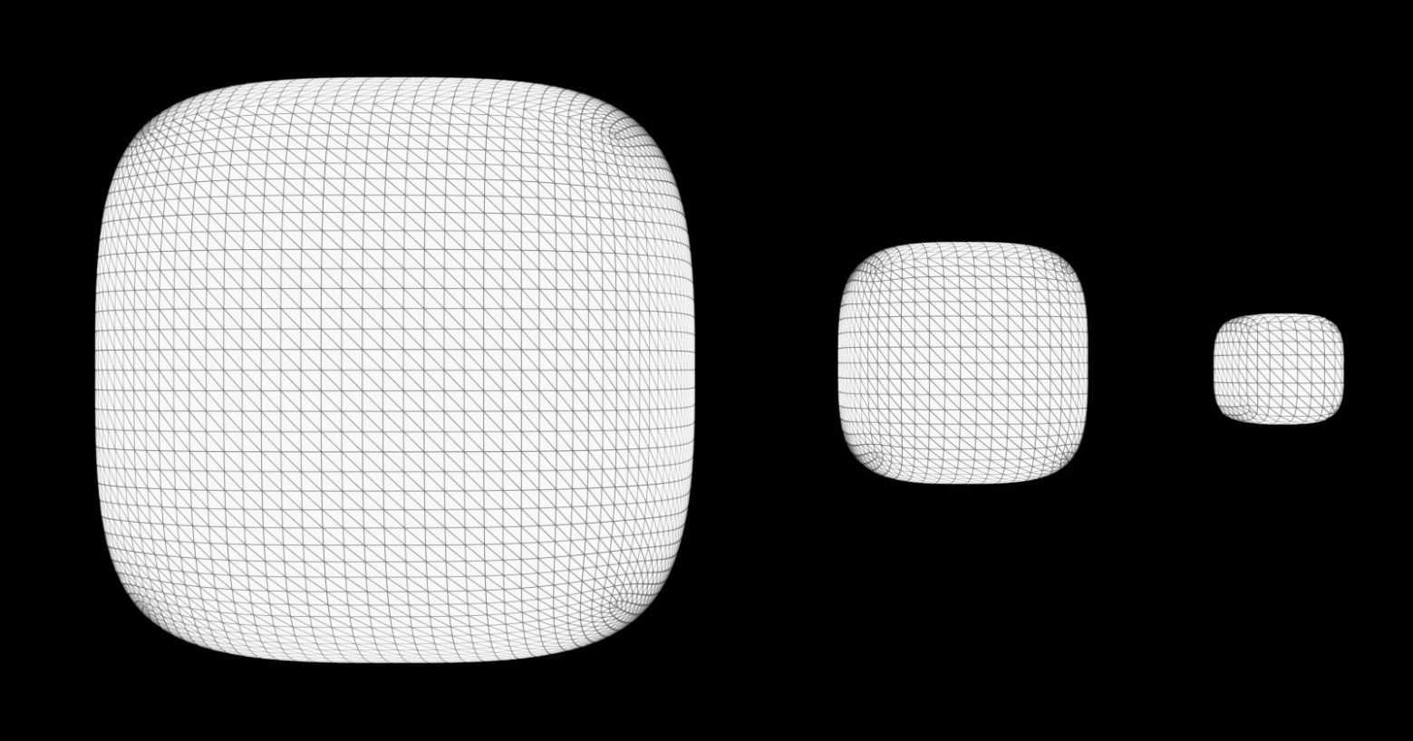
Adaptive subdivision |
Crease Weight
The crease weight parameter controls the sharpness of the mesh edges and corners. With a greater crease weight, the mesh is more resistant to smoothing at its intersections, so the edges and corners appear sharper. Smaller values produce more deformation of the mesh around the edges and result in smoother transitions between polygons.
The input type for this parameter is a number greater than or equal to 0.

Crease weight: 0, 0.5, 1 |
Boundary
The boundary is commonly used for meshes with unconnected patches that have a common boundary, which is also called a seam. The boundary parameter describes how these patches meet along the seam — only at the edges only or at the edges and corners.
With the default Edge only option selected, the face boundary is smoothed at the corners, but may produce unwanted gaps across the boundary. The Edge and corner option keeps the corners constrained, so that the boundary remains sharp.
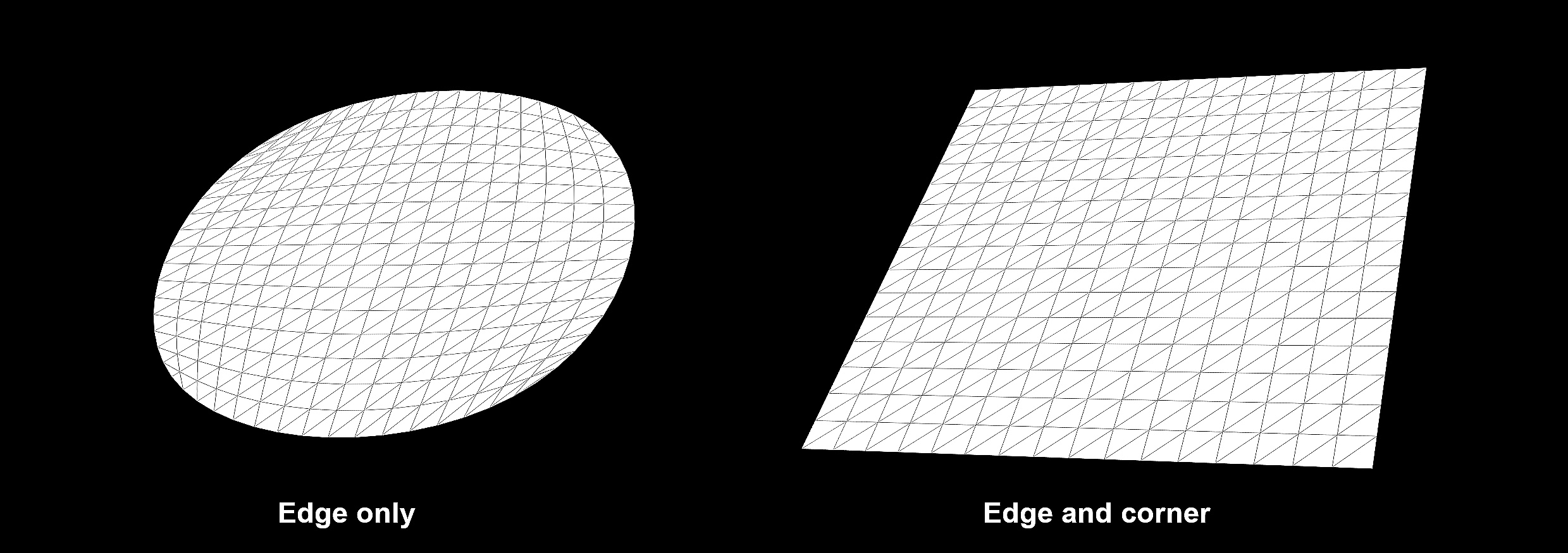
Displacement boundary: Edge only, Edge and corner |
Displacement Map
The parameter is used as an input for a texture map that will be applied for the mesh deformation.
AMD Radeon ProRender best supports grayscale textures as displacement maps. Color textures should be converted to grayscale textures by using color management tools.